
Lora Smart Agriculture & Remote Monitoring System
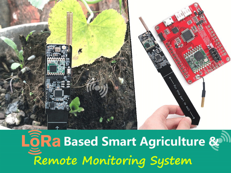
In this project, we will learn how to build an IoT Lora Smart Agriculture & Remote Monitoring System, we will use the LoRa soil moisture sensor and Maduino Lora module.
1. Overview: IoT LoRa Based Smart Agriculture
In this project, we are going to learn about IoT LoRa Based Smart Agriculture & Remote Monitoring System. Smart Agriculture means monitoring environmental conditions that influence crop production & track livestock health indicators. LoRa based Internet of Things (IoT) technology for agriculture enables efficiencies that reduce environmental impact, maximize yield, and minimize expenses. Smart agriculture use cases based on LoRa devices and the LoRaWAN protocol have demonstrated significant improvements, such as a 50% water reduction for commercial farms.
In this project, we will use the LoRa soil moisture sensor based on the Atmega328P microcontroller, LoRa Module RFM95 & AHT10 Humidity/Temperature Sensor. The AHT10 Digital Humidity & Temperature Sensor measures the local air temperature & humidity. The Capacitive Soil Moisture Sensor will measure the Soil Humidity/Moisture. Hence all the measured data can be sent wirelessly up to 15km distance and can be read by the receiver. Both the transmitter and receiver are designed using the LoRa Module.
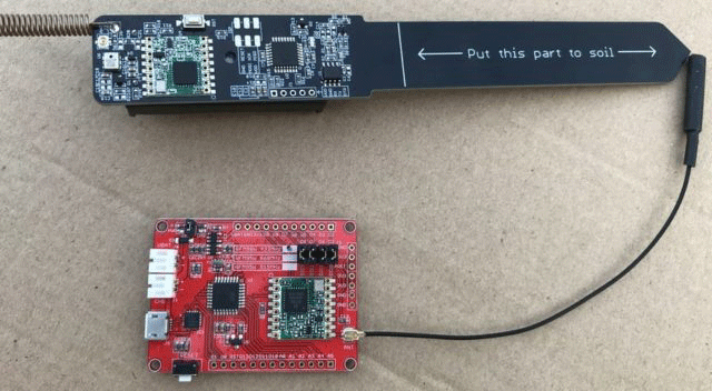
The transmitter operates on low power mode. Using a AAA Battery the device can be operated over a year. The device power can be controlled and data sending intervals can be increased as per requirement. Thus the advantage of this technology includes long-range, low-power wireless qualities that enable the use of low-cost sensors to send data from the farm to the Cloud where it can be analyzed to improve operations.
2. Bill of Materials
The following are the components required for making this IoT LoRa Network Based Smart Agriculture Project. We need a few LoRa Agriculture sensors like the Soil Moisture sensor to measure Soil Moisture. We can measure the environmental parameter like surrounding humidity & temperature. For this AHT10 is the best suitable Sensor.
Instead of buying separate sensors and assembling on a board is a tough and time-consuming task. So I purchased a combined sensor board assembled on a PCB Board. Both the transmitter & receiver part PCB Board with component assembled on it can be purchased from the below link.
Required Materials
| No. | Material Name | Description | Quantity | Link |
| 1 | Lora Soil Moisture Sensor | Transmitter | 1 | |
| 2 | Maduino Lora Radio | Receiver | 1 |
https://www.makerfabs.com/maduino-lora-radio-433m-868m-915m.html |
| 3 | CP2104 USB2UART Converter | FTDI Module | 1 |
https://www.makerfabs.com/cp2104-usb-to-serial-converter.html |
3. LoRa Transmitter: Soil Moisture Sensor + AHT10 Humidity/Temperature Sensor
The transmitter part consists of a Lora soil moisture sensor and AHT10 Humidity/ Temperature Sensor. The microcontroller used in this board is Atmel’s Atmega328P which supports Arduino programming. The AHT10 sensor collects local air temperature & humidity. The Capacitive Soil Moisture Sensor detects the soil humidity. The sensor is based on 555-Timer IC. The Lora Radio and the Soil Moisture Sensor must have the same work frequency. Otherwise, it receives nothing from another. The transmitter transmits the local environment data to the gateway using the LoRa module RFM95.

The Lora transmitter is powered by a pair of AAA batteries. The device transmits the data regularly after the interval of a few minutes and then goes to sleep mode for saving the battery power. The sensor function could be shut down or they can be only powered ON for a short time based on code and hardware setup. Thus because of sleep mode and low power consumption mode, the battery life can be extended up to several months. The capacitive soil Moisture sensor is coated with waterproof paint, so it doesn’t have any corrosion effect even the sensor is dipped in the soil for a long time. The module suits for applications for smart-farm, irrigation, agriculture, etc.
The ATmega328 chip has default Arduino bootloader and thus can be easily programmed using Arduino IDE. We just need a USB-to-TTL converter module.
3.1 Power Consumption & Sleep Mode
MCU Power Consumption at 1MHz, 1.8V, 25°C.
- Active Mode: 0.2mA
- Power-down Mode: 0.1µA
- Power-save Mode: 0.75µA (Including 32kHz RTC)
4. Lora Receiver: Maduino Lora Radio (433M/868M/915M)
The Maduino Lora Radio Receiver is a mainboard based on the ATmega328 and 433MHZ/ 868MHz/ 915MHz RFM95 LoRa module. The Maduino LoRa Radio allows the user to send data and reach extremely long ranges at low data-rates. It provides ultra-long range spread spectrum communication and high interference immunity whilst minimizing current consumption. It has Arduino pro mini 3.3V 8MHz bootloader on this board and uses the CP2104 as USB to serial to upload the code using Arduino IDE. In this LoRa Smart Agriculture project, we will use it as a Receiver Gateway.
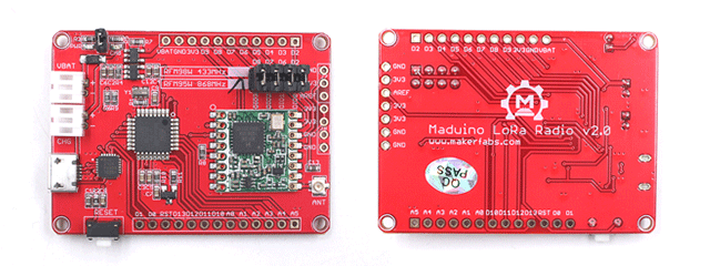
Features:
- BAT Input Voltage: 3.4-4.2V
- Integrated Power Control System
- 127 dB Dynamic Range RSSI
- Uses the License-free ISM band: "European ISM" @ 433MHz/868MHz/915MHz
- +5 to +20 dBm up to 100 mW Power Output Capability (power output selectable in software)
- ~100mA Peak during +20dBm transmit, ~30mA during active radio listening
- Range of approx.2KM, depending on obstructions, frequency, antenna, and power output
5. Setting up Lora Soil Moisture Transmitter Part
In order to upload the code to the transmitter part, you need to solder a 5 pin male header pin. So first solder the male header pin here. Or you can use Makerfabs CP2104 USB to Serial Converter CP2104 USB to Serial Converter directly, which is specially designed for the Lora soil moisture sensor programming.
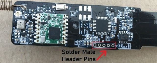
Now you need to connect USB-to-UART Module ;to upload the code the Atmega328 chip using Arduino IDE. Make a connection between the USB-to-UART module as follow. You can use a USB-to-Serial tool or directly use CP2014 USB2UART.
| Lora Soil Moisture Sensor | USB-to-UART Tool |
| 3V3 | 3V3 |
| GND | GND |
| RX | TXD |
| TX | RXD |
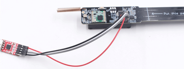
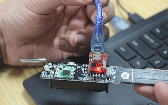
Note that the DTR in the USB-to-UART converter is needed to connect to the "Reset" pin for Arduino sketch uploading. If there is no DTR, you may need to press the "reset" button manually for uploading the code.
Install AAA battery on the backside of the module.
Now in order to program the Board using Arduino IDE for Lora agriculture sensor Board, there is already a default package board installed on Arduino IDE.
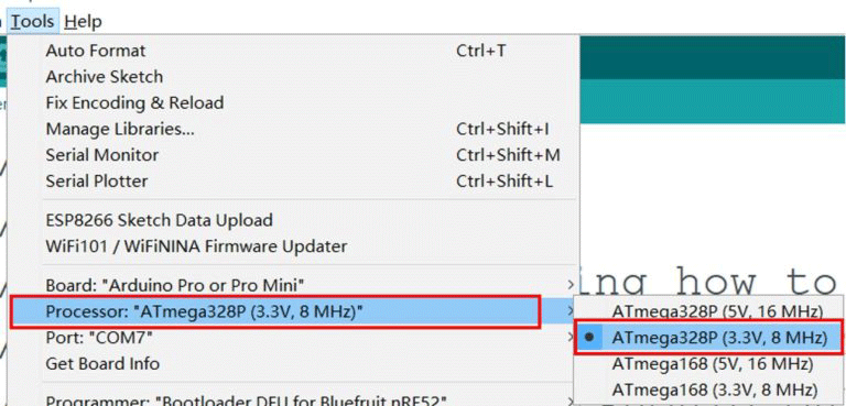
From the top Arduino IDE menu, select Tools→ Board→ Arduino Pro or Pro Mini. Also select Tools→ Processor→ Atmega328P(3.3V,8Mhz).
6. Setting up Lora Receiver Part
The Lora Receiver doesn’t need any USB-to-UART module as it can be directly programmed using Micro-USB data cable.
The board uses the same package for programming. So Select the Arduino Pro or Pro mini & ATmega328P (3.3V,8Mhz) Board.

7. Transmitter Code
The transmitter code is divided into 3 files:
1. Main.ino File
2. I2C_AHT10.cpp File
3. I2C_AHT10.h File
But before that, you need to add RFM95 library to the Arduino IDE. So download the RFM95 Library from the link below and add it to the library folder. Download LoRa RFM95 Library.
Modify the frequency macro according to your board is 433Mhz or 868Mhz or 915Mhz.
If your Lora board is 433MHz:
| #define RF95_FREQ 433.0 |
If your Lora board is 868MHz:
| #define RF95_FREQ 868.0 |
If your Lora board is 915MHz:
| #define RF95_FREQ 915.0 |
7.1. Main.ino File
|
#include <SPI.h> #include "I2C_AHT10.h" int sensorPin = A2; // select the input pin for the potentiometer void sensorPowerOn(void) #define RFM95_CS 10 // Change to 434.0 or other frequency, must match RX's freq! // Singleton instance of the radio driver void setup() pinMode(RFM95_RST, OUTPUT); pinMode(sensorPowerCtrlPin, OUTPUT); //while (!Serial); Wire.begin(); //Join I2C bus Serial.println("Marduino LoRa TX Test!"); // manual reset while(!rf95.init()) { //rf95.setModemConfig(Bw125Cr48Sf4096); //Defaults after init are 434.0MHz, modulation GFSK_Rb250Fd250, +13dbM // Defaults after init are 434.0MHz, 13dBm, Bw = 125 kHz, Cr = 4/5, Sf = 128chips/symbol, CRC on // The default transmitter power is 13dBm, using PA_BOOST. //dht.begin(); int16_t packetnum = 0; // packet counter, we increment per xmission void loop() // Reading temperature or humidity takes about 250 milliseconds! sensorPowerOn();// if (humiditySensor.available() == true) //Print the results } delay(100); Serial.print(F("Moisture ADC : "));
String message = "#"+(String)packetnum+" Humidity:"+(String)humidity+"% Temperature:"+(String)temperature+"C"+" ADC:"+(String)sensorValue; // Send a message to rf95_server uint8_t radioPacket[message.length()+1]; radioPacket[message.length()+1]= '\0'; Serial.println("Sending..."); delay(10); Serial.println("Waiting for reply..."); delay(10); |
7.2. I2C_AHT10.cpp File
|
#include "I2C_AHT10.h" /*--------------------------- Device Status ------------------------------*/ _deviceAddress = AHT10_DEFAULT_ADDRESS; //We had hoped the AHT10 would support two addresses but it doesn't seem to if (isConnected() == false) //Wait 40 ms after power-on before reading temp or humidity. Datasheet pg 8 //Check if the calibrated bit is set. If not, init the sensor. //Immediately trigger a measurement. Send 0xAC3300 delay(75); //Wait for measurement to complete uint8_t counter = 0; //This calibration sequence is not completely proven. It's not clear how and when the cal bit clears //Check that the cal bit has been set //Mark all datums as fresh (not read before) return true; //Ping the AHT10's I2C address //If IC failed to respond, give it 20ms more for Power On Startup _i2cPort->beginTransmission(_deviceAddress); return false; /*------------------------ Measurement Helpers ---------------------------*/ uint8_t AHT10::getStatus() //Returns the state of the cal bit in the status byte //Returns the state of the busy bit in the status byte bool AHT10::initialize() bool AHT10::triggerMeasurement() //Loads the if (_i2cPort->requestFrom(_deviceAddress, (uint8_t)6) > 0) uint32_t incoming = 0; incoming |= midByte; sensorData.temperature = (uint32_t)midByte << (8 * 2); //Need to get rid of data in bits > 20 //Mark data as fresh //Triggers a measurement if one has not been previously started, then returns false if (isBusy() == true) readData(); bool AHT10::softReset() /*------------------------- Make Measurements ----------------------------*/ float AHT10::getTemperature() delay(75); //Wait for measurement to complete uint8_t counter = 0; readData(); //From datasheet pg 8 //Mark data as old return tempCelsius; float AHT10::getHumidity() delay(75); //Wait for measurement to complete uint8_t counter = 0; readData(); //From datasheet pg 8 //Mark data as old return relHumidity; |
7.3. I2C_AHT10.h File
|
#ifndef __I2C_AHT10_H__ #include <Arduino.h> #define AHT10_DEFAULT_ADDRESS 0x38 enum registers class AHT10 struct struct public: //Measurement helper functions //Make measurements |
8. Receiver Code
|
#include <SPI.h> int count=0; void setup() // manual reset if (rf95.recv(buf, &len)) // Send a reply |
9. IoT LoRa Based Smart Agriculture & Remote Monitoring System
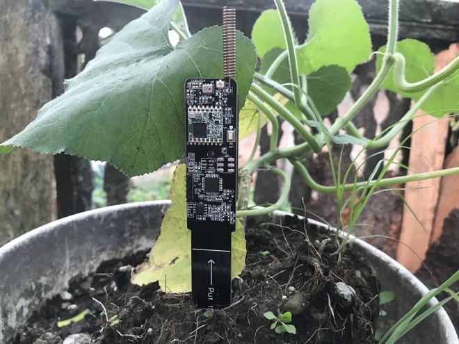
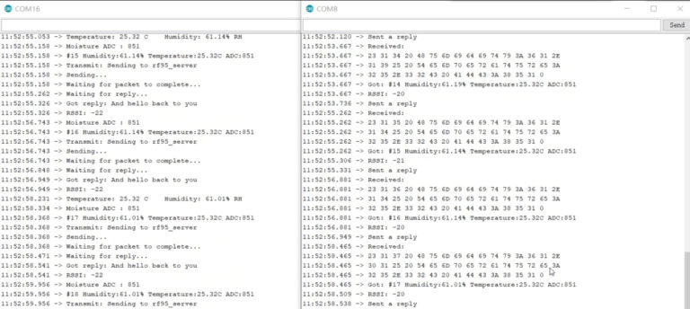
Let us check now a simple demonstration of LoRa based Smart Agriculture. Now you can open the serial monitor for both the transmitter and receiver. The Lora transmitter and receiver will get started and communicate with each other.
The transmitter end will read the soil moisture data in ADC which can be converted to a percentage value (Refer to this Article...). Similarly, the AHT10 will collect Air Humidity and Temperature Data. The data is transmitted to the gateway.
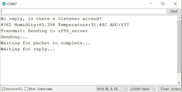

The transmitter will send the data and then goes to deep sleep mode or power saving mode. During the data transmission mode, it consumes around 0.2mA of power. While in the power-save mode the current get reduced to 0.75µA. Battery life can be increased to several months by increasing the interval of data transmission.
Well, that’s all from IoT Lora Based Agriculture Network. If you have any further questions or some special customized requirement based on those Lora IoT boards, feel free to contact service@makerfabs.com.
You can also check this review from Happy DIY Home when buying soil moisture sensors.
This article is originally posted on How2electronics.
You can also learn from this video tutorial made by How2electronics:
You can also check this review from Happy DIY Home when buying soil moisture sensors.


 Previous


is really nice and the users are genuinely sharing fastidious
thoughts.